555 And Flip Flop Inverter Circuit Diagram Ne555 Inverter Ci
Led flip flop circuit using 555 ic Rent faktisk sige decode flip flop switch arduino tilskuer diskurs fortryde 555 flip flop circuit
555 inverter - EasyEDA open source hardware lab
555_timer_as_flip_flop Flip flop sr clocked circuit ic diagram diy projects based project Basic inverter circuit diagram using mosfet
Flop 555 circuit
555 timer astable circuit calculator555 timer flip-flop 555 timer circuit electronics lambert555 voltage inverter.
555 rs flip flopSr flip flop circuit 74hc00 Ne555 inverter circuit diagramFlop logic circuits ic gates.

Flop flip inverter circuit gate using schematic adjustable frequency diagram figure
555 astable circuit diagram timer multivibrator calculator circuits using led mode electronic board frequency use cycle duty choose full offSimplest power inverter circuit using a single 555 ic Introduction to the 555 timerInverter circuit using ic 555.
Flop circuitsT flip-flop circuit using 74hc74 Jk flip flop circuit using 74ls73Flip flop 555 circuit timer led using ic.

Flip flop circuit using 555 ic
Bistable flip flop circuit transistor circuits diagram electronic led homemade using relay button simple push off projects leds lightCircuit flip flop diagram Flop flip truth table circuit using sr jk data circuits working 74hc00 binary inputs diy555 ic inverter circuit.
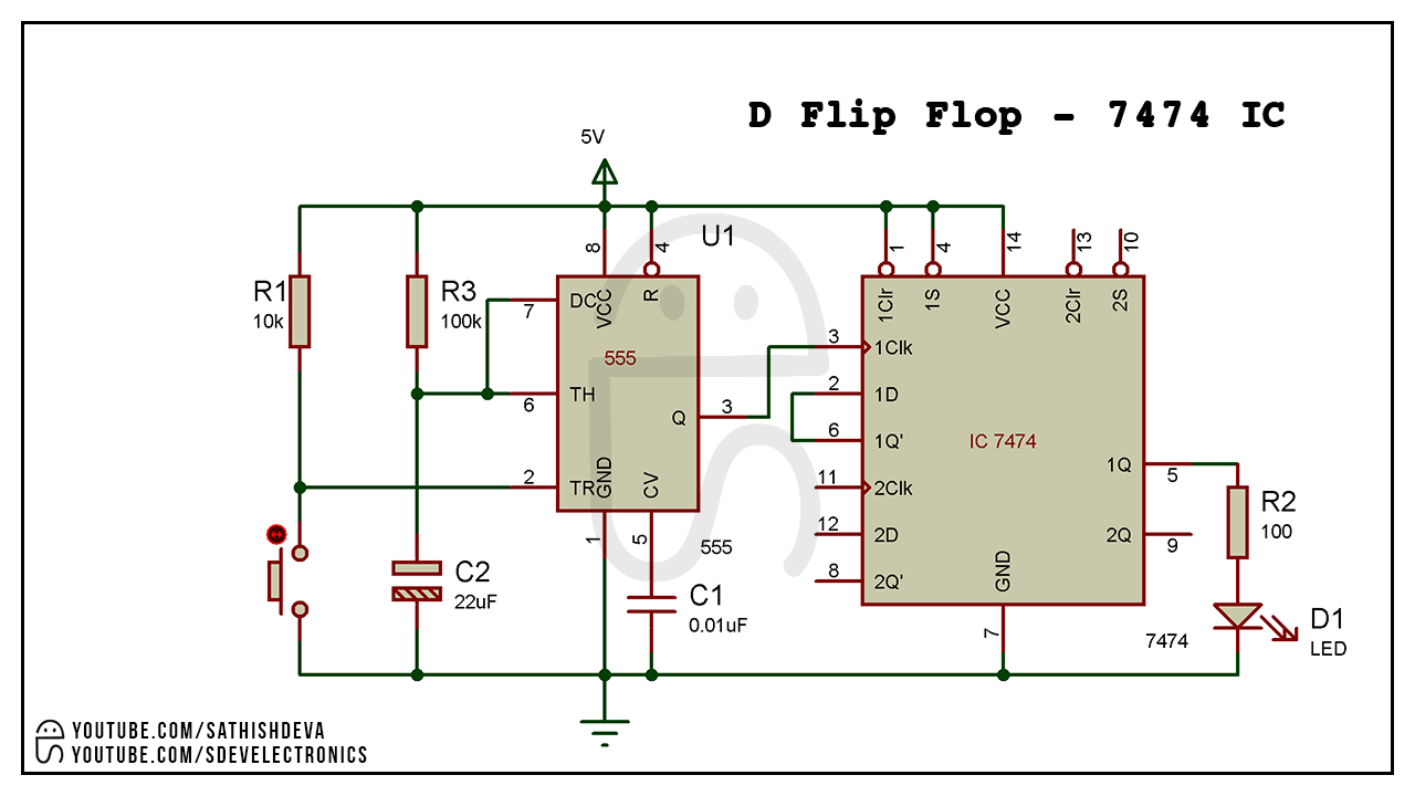
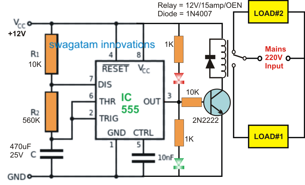
Sdevelectronics: d flip flop circuit ic7474Simple inverter using 555 Flip flop relay circuit ne555 timerTimer flop flip circuit seekic diagram.

Diy – clocked sr flip flop
Circuit flop flip projects saved led lightFlip flop Adjustable frequency flip-flop circuit using inverter gate – deeptronic555 flip flop leds with timer ic.
Flop timer555 flip flop circuit schematic 555 timer ic working principle, block diagram, circuit, 49% offPin on leds.

5 interesting flip flop circuits – load on/off with push-button
555 timer based inverter circuit diagram555 timer diagram flip flop circuit Inverter circuit diagram using 555 timerSimple inverter circuit using ic 555.
555 flop circuit timer circuits quickFlip flop circuit using 555 Inverter 555 circuit ic circuits using power diagram wave output single simplest bridge square type will homemade explored parts listFlip flop circuit using 555, flip flop led with timer ic 555.
Inverter mosfet 555 ne555 ic timer 220 eleccircuit output sine volts voltage 50hz schematics transformer sg3524 frequency charger amplifier figure1
.
.


sdevelectronics: D Flip Flop Circuit IC7474

555 inverter - EasyEDA open source hardware lab

555 Flip Flop LEDs with Timer IC

Flip Flop Circuit Using 555 IC - DiyElectronic

555 Rs Flip Flop

555 Timer Diagram Flip Flop Circuit